Export Tools
This chapter describes the export options available for the active model and how output files are configured.
Export Hydrodynamic OilFlow2D

Dialog Window
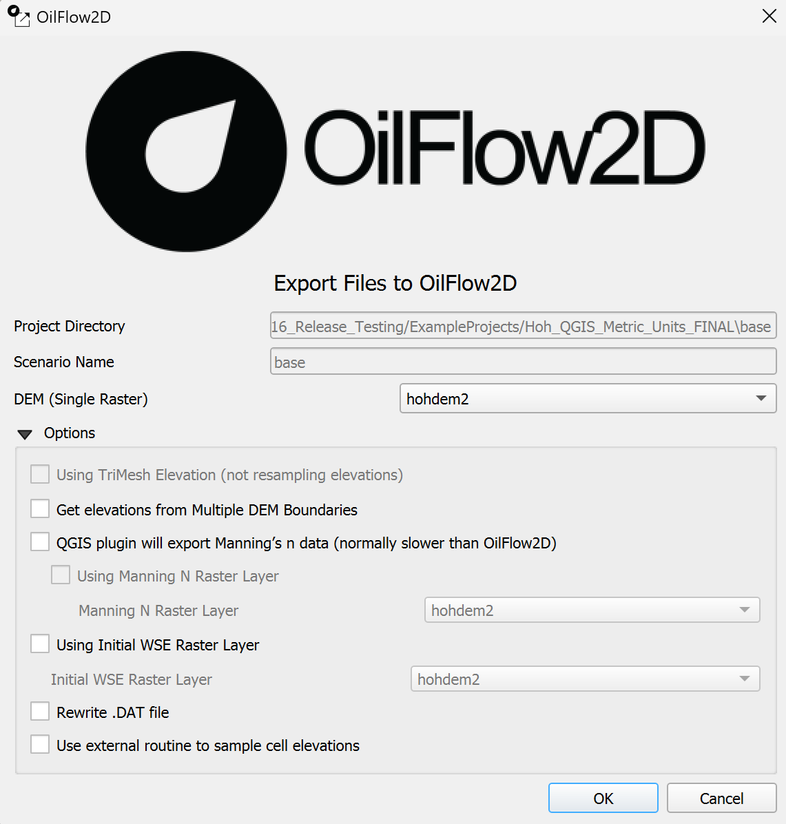
The following dialog is the main interface for configuring and initiating the export process for the OilFlow2D model. It gathers information about input layers and specific components to be included in the export.
Dialog Controls
The following table describes the controls available in the Export dialog.
| Control Name | Type | Description |
|---|---|---|
| Project Directory | Text Field | Displays the full path to the current scenario's output directory within the project. (Read-only) |
| Scenario Name | Text Field | Displays the name of the current scenario being exported. (Read-only) |
| DEM (Single Raster) | Dropdown | Select the single raster layer representing the bed topography/elevation. Enabled only if neither 'Using TriMesh Elevation' nor 'Get elevations from Multiple DEM Boundaries' is active. Populated with available raster layers. |
| Using TriMesh Elevation (not resampling elevations) | Checkbox | Enable to use elevation data directly from the 'TriMesh' layer vertices/nodes instead of resampling from a DEM raster. Disables DEM selection options. Automatically checked if mesh was generated using \"Generate TriMesh with Elevation\" tool. |
| Get elevations from Multiple DEM Boundaries | Checkbox | Enable to use elevation data based on boundaries defined in a 'MultipleDemBoundaries' layer. Disables the 'DEM (Single Raster)' dropdown. Requires the 'MultipleDemBoundaries' layer to be present. |
| Using Manning N Raster Layer | Checkbox | Enable to use Manning's n values sampled from a selected raster layer instead of a vector layer. Enables the 'Manning N Raster Layer' dropdown. |
| Manning N Raster Layer | Dropdown | Select the raster layer containing Manning's n values. Enabled only when 'Using Manning N Raster Layer' is checked. Populated with available raster layers. |
| Using Initial WSE Raster Layer | Checkbox | Enable to use initial water surface elevation (WSE) values sampled from a selected raster layer. Enables the 'Initial WSE Raster Layer' dropdown. |
| Initial WSE Raster Layer | Dropdown | Select the raster layer containing initial WSE values. Enabled only when 'Using Initial WSE Raster Layer' is checked. Populated with available raster layers. |
| Rewrite .DAT file | Checkbox | Enable to force regeneration and overwriting of the main RiverFlow2D control file ('.dat'). |
| Use external routine to sample cell elevations | Checkbox | Enable to use the external executable ('ASCIISamplingC.exe') for sampling elevation values for mesh cells/centroids. This might be faster or handle large datasets differently than the internal QGIS methods. |
| OK | Button | Confirms the selections and initiates the export process based on the chosen options and detected layers. |
| Cancel | Button | Closes the dialog without exporting any files. |
Workflow
The typical workflow for using the Export Files to RiverFlow2D tool is as follows:
-
Ensure all required input layers (e.g., 'TriMesh', 'Manning N'/'Nr'/'Nz', optional layers like 'Boundary Conditions', 'Weirs', 'Bridges', DEM rasters etc.) are loaded into the QGIS project and meet the requirements (See Section 2.1.4). Make sure the 'Domain Outline' layer, if present, is not in editing mode.
-
Activate the tool from the OilFlow2D plugin menu or toolbar. This will open the Export Files to OilFlow2D dialog (Figure 2.2).
-
Verify that the Project Directory and Scenario Name are correctly displayed, reflecting the current project and active scenario.
-
Click OK to start the export process, or alternately if you need to set additional parameters, review the Options group box.
-
(Optional) Configure if Manning's roughness data should be sourced from a raster layer.
-
(Optional) Select the checkbox to use a raster for Initial Water Surface Elevation.
-
(Optional) Decide whether to use the external elevation sampling routine and whether to force rewriting the '.dat' file.
-
Click OK.
-
The tool performs requirement checks (e.g., layer existence, CRS compatibility, empty layers).
-
If checks pass, the tool proceeds with the export. It creates a centroids layer, samples necessary data (elevation, roughness, initial WSE) based on the selected options, and exports various component files ('.TGates', '.TWeirs', '.TBridges', '.TDams', '.THydnet', '.OBC', etc.) based on the presence of corresponding layers in the QGIS project (e.g., 'Gates', 'Weirs', 'Bridges', 'DamBreach', 'Channels1D', 'Boundary Conditions', etc.).
-
Finally, it generates the primary model input files: the geometry/mesh file ('.fed') and the control data file ('.dat'). Other auxiliary files like '.plt' and '.qgisunits' may also be created.
-
All exported files are saved in a subdirectory named after the current scenario within the main project directory. A confirmation message will appear upon successful completion, or error messages will be shown if issues occur.
Requirements
Before using the Export tool, ensure the following requirements are met:
-
A QGIS project must be loaded.
-
The project must have a defined current scene (scenario). This determines the output subdirectory and file naming.
-
A mesh layer named 'TriMesh' must be present and active in the layer panel. This provides the core mesh geometry.
-
At least one Manning's roughness source must be available and active: either a vector layer named 'Manning N' or raster layers named 'Manning Nr' or 'Manning Nz'.
-
Having both 'Manning N' (vector) and 'Manning Nz' (raster) active simultaneously is not allowed.
-
Having both 'Manning N' (vector) and 'Manning Nr' (raster) active simultaneously is not allowed.
-
-
All layers must not be in editing mode. Save any edits and toggle editing off for this layer before exporting.
-
If the option 'Get elevations from Multiple DEM Boundaries' is to be used, a layer named 'MultipleDemBoundaries' must be present.
-
All relevant input layers (mesh, DEMs, roughness sources, component layers) must have compatible Coordinate Reference Systems (CRS).
-
Active input layers should not be empty (contain no features or valid data).
Failure to meet these requirements will likely result in error messages displayed in the QGIS message bar and prevent the export from completing.
Technical Details
-
The primary output files generated are the model's mesh/geometry file ('.fed') and the main input control data file ('.dat'). A plot data file ('.plt') and a units file ('.qgisunits') are also typically generated.
-
Numerous other component-specific input files are generated conditionally, based on the presence of layers with specific names in the QGIS project. These include:
.dOut('Domain Outline'),.TGates('Gates'),.IRT('InternalRatingTable'),.TWeirs('Weirs'),.TDams('DamBreach'),.TBridges('Bridges'),.THydnet('Channels1D'),.OBC/.OBCP('Boundary Conditions'),.OBS('Observation Points'),.source('Sources'),.scour('ScourFromPiers', 'ScourFromAbutment'),.lswmm('LSWMM'),.MannN/.MannN2('Manning N' vector/raster),.Linf/.Lrain/.Wind/.initConc(Related infiltration, rain, wind, initial concentration layers). -
All exported files are saved within a subdirectory named after the current project scene (scenario name), located within the main project directory identified in the dialog.
-
A temporary centroids layer is created during the process using
centroide_layer().
Export OILW File
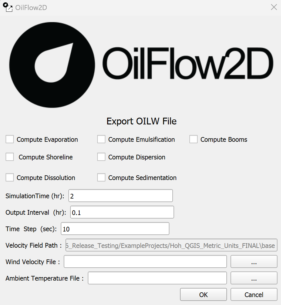
This dialog allows the user to configure and export the necessary input file for running oil weathering and transport simulations within OilFlow2D.
Dialog Controls
The following table describes the controls available in the Export OILW File dialog.
| Control Name | Type | Description |
|---|---|---|
| Compute Evaporation | Checkbox | Enable the evaporation process simulation. |
| Compute Emulsification | Checkbox | Enable the emulsification process simulation. |
| Compute Booms | Checkbox | Enable the simulation of containment booms. Requires a 'Booms' layer. |
| Compute Shoreline | Checkbox | Enable the shoreline interaction simulation. |
| Compute Dispersion | Checkbox | Enable the dispersion process simulation. |
| Compute Dissolution | Checkbox | Enable the dissolution process simulation. |
| Compute Sedimentation | Checkbox | Enable the sedimentation process simulation. |
| SimulationTime (hr) | Text Field | Enter the total simulation duration in hours. |
| Output Interval (hr) | Text Field | Enter the time interval for writing output results in hours. |
| Time Step (sec) | Text Field | Enter the simulation time step in seconds. |
| Velocity Field Path | Text Field (Read-only) | Displays the path to the directory containing the velocity field data (typically the current scenario directory). |
| Wind Velocity File | Text Field | Enter the name of the file containing wind velocity data. Use the browse button to select. |
| ... (Browse Wind) | Button | Opens a file dialog to select the Wind Velocity File. |
| Ambient Temperature File | Text Field | Enter the name of the file containing ambient temperature data. Use the browse button to select. |
| ... (Browse Temp) | Button | Opens a file dialog to select the Ambient Temperature File. |
| OK | Button | Confirms the settings and initiates the export process. |
| Cancel | Button | Closes the dialog without exporting the file. |
[]{#tab:oilw_controls_en label="tab:oilw_controls_en"}
Workflow
The typical workflow for using the Export OILW File tool is as follows:
-
Ensure the required 'OilSpills' point layer and/or 'OilSpillsRelease' line layer are loaded into the QGIS project and meet the requirements (See Section 2.2.3). The attributes of these layers define the spill locations/sources and properties.
-
If simulating booms, ensure the required 'Booms' line layer is loaded.
-
Ensure the main OilFlow2D hydrodynamic simulation files (especially
.dat) have already been exported for the current scenario using the main export tool (Section 2.1). -
Activate the tool from the OilFlow2D plugin menu or toolbar (usually under a submenu like 'Modules' or similar).
-
The Export OILW File dialog opens (Figure 2.3).
-
Check or uncheck the various 'Compute...' options (Evaporation, Emulsification, Booms, Shoreline, Dispersion, Dissolution, Sedimentation) as required for the simulation.
-
Enter the desired 'SimulationTime', 'Output Interval', and 'Time Step'. These values may be pre-populated from a parameter file ('Oilwparamxport.txt') if it exists in the scenario directory.
-
Verify the 'Velocity Field Path' is correct (it should point to the current scenario directory).
-
Enter the filenames for the 'Wind Velocity File' and 'Ambient Temperature File' or use the browse buttons ('...') to select them. These files must exist in the scenario directory.
-
Click OK.
-
The tool performs requirement checks (e.g., layer existence, CRS compatibility, non-empty control fields, file existence within scenario folder).
-
If checks pass, the tool generates the Oil Weathering input file ( texttt.OILW) in the current scenario directory using data from the dialog and the relevant spill/boom layer attributes.
-
If an 'OilSpillsRelease' layer is present, separate spill path files ('.pth') are generated for each feature using
spillReleaseFile(). -
If the 'Compute Booms' option is checked and a 'Booms' layer is present, a booms data file ( texttt.booms) is generated using
spillBoomFile(). -
The tool then reads the existing
.datfile for the scenario, updates a specific flag to indicate oil spill simulation is active (flag set to 3), and rewrites the.datfile. -
An oil parameters export file ('Oilwparamxport.txt') is created or updated in the scenario directory to store the dialog settings.
-
The OilFlow2D executable (specifically
RiverFlow2DDIP.exe) is optionally launched automatically using the generated files. -
A confirmation or error messages will be shown in the QGIS message bar.
Requirements
Before using the Export OILW File tool, ensure the following requirements are met:
-
A QGIS project must be loaded with a defined current scene (scenario).
-
The main OilFlow2D hydrodynamic export (Section 2.1) must have been run previously for the current scenario, creating the necessary base files like
.datand.OUTFILES. -
At least one oil source layer must be present and active: 'OilSpills' (point layer for instantaneous spills) or 'OilSpillsRelease' (line layer for continuous release paths). These layers must contain features with the specific attributes required by the
fileOilSpills()function (e.g., density, viscosity, timing, dispersion, evaporation parameters, etc.). -
If the 'Compute Booms' option ( textttcBox_booms) is checked, a line vector layer named 'Booms' must be present and active. It needs appropriate attributes for boom properties.
-
The source layers ('OilSpills', 'OilSpillsRelease', 'Booms') must not be empty if they are present.
-
All layers involved must have compatible Coordinate Reference Systems (CRS). The tool performs a check.
-
The required input fields in the dialog (SimulationTime, Output Interval, Wind Velocity File, Ambient Temperature File) must not be empty.
-
The selected Wind Velocity File and Ambient Temperature File must reside within the current scenario directory.
Failure to meet these requirements will result in error messages and prevent the export from completing.
Technical Details
-
The primary output file generated by this tool is the Oil Weathering input file ( texttt.OILW).
-
If continuous spills are defined via an 'OilSpillsRelease' layer, corresponding path files ( texttt.pth) are also generated for each release source.
-
If booms are enabled and a 'Booms' layer exists, a texttt.booms file is generated.
-
The tool modifies the existing main OilFlow2D control data file ( texttt.dat) by reading it ( textttreadDAT()) and rewriting it ( textttrewriteDAT()) with a specific flag (index 15) set to 3 to enable the oil spill module in the OilFlow2D engine.
-
The
.OILWfile is generated by thefileOilSpills()function, which reads control data from the dialog and detailed spill information from the attributes of the 'OilSpills' and/or 'OilSpillsRelease' layer features. It includes sections for [Trajectory], [Evaporation], [Emulsification], [Dissolution], [Dispersion], [Sedimentation], and [Shoreline] parameters based on the attributes and dialog settings. -
A parameter file ('Oilwparamxport.txt') is saved in the scenario directory by the
oilwParameterFile()function (called fromtools.py) to persist the dialog settings (time, output interval, wind file, temp file). -
The tool attempts to automatically launch the OilFlow2D executable (specifically
RiverFlow2DDIP.exe, which handles oil spills) using the generated.OILWand modified.datfiles via thecallRiverFlow()function.