New Project / Scenario Tool

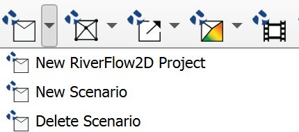
This chapter describes the tools related to creating and managing new projects and scenarios. Within the New RiverFlow2D Project menu, the following tools are available:
New RiverFlow2D Project
Dialog Window
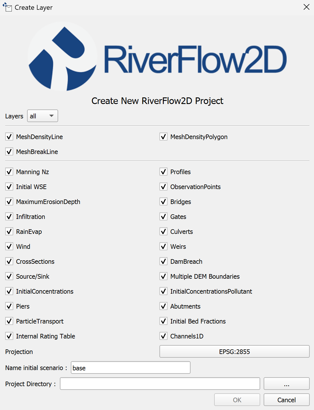
The New RiverFlow2D Project dialog allows the user to specify the project name, initial scenario name, project location, and select the components to be included in the initial setup.
Dialog Controls
The dialog contains the following controls:
| Control | Type | Description |
|---|---|---|
| Set Current Project Projection | Button | Button to open the QGIS Project Properties dialog to select or verify the Coordinate Reference System (CRS) for the project. |
| Projection Display | Read-only field | Read-only field showing the selected project CRS (e.g., EPSG code). |
| Project Name | Text input field | Text input field to specify the name for the new project. This name will be used for the main project folder and the QGIS project file. |
| Name Initial Scenario | Text input field | Text input field to specify the name for the first scenario within the project. A subfolder with this name will be created. |
| Project Directory | Text input field | Text input field displaying the path to the directory where the project folder will be created. |
| Browse Button (...) | Button | Button next to Project Directory that opens a directory selection dialog. |
| Components Checkboxes | Checkbox Group | A series of checkboxes allowing the user to select which optional model components and data layers should be initialized for the project. Options include: Density Line, Density Polygon, Manning's Coefficient (Nz), Infiltration Parameters, Bridge/Culvert Scour (MaximumErosionDepth), Sediment Transport (ParticleTransport), Pollutant Transport (InitialConcentrationsPollutant), Mesh Refinement Areas (MeshBreakLine, MeshDensityLine, MeshDensityPolygon), Flow Obstructions (Piers, Abutments), Wind, Weirs, CrossSections, DamBreach, Source/Sink, Multiple DEM Boundaries, InitialConcentrations, Initial Bed Fractions, Internal Rating Table, Channels1D, Gates, Culverts, Initial WSE, Profiles, ObservationPoints. (All are checked by default). |
| Ok | Button | Button to confirm the settings and create the new project. |
| Cancel | Button | Button to close the dialog without creating a project. |
Initial Layers
The tool creates several initial GeoPackage layers within the shape subdirectory of the new scenario, based on the components selected in the dialog. The following table describes the layers created by default:
| Layer Name | Type | Description |
|---|---|---|
| MeshDensityLine | Line | Defines lines along which mesh density is controlled. |
| MeshDensityPolygon | Polygon | Defines areas within which mesh density is controlled. |
| MeshBreakLine | Line | Enforces mesh element edges along these lines (e.g., levees, walls). |
| Domain_Outline | Polygon | Defines the outer boundary of the 2D model domain. |
| Boundary Conditions | Line | Defines locations where boundary conditions (inflow, outflow, WSE) are applied. |
| Manning Nz | Polygon | Defines zones with specific anisotropic Manning's roughness coefficients. |
| Initial WSE | Polygon | Defines zones with specific initial water surface elevations. |
| MaximumErosionDepth | Polygon | Defines zones specifying the maximum allowable bed erosion depth (for scour). |
| Infiltration | Polygon | Defines zones with specific soil infiltration parameters. |
| RainEvap | Polygon | Defines zones where rainfall and/or evaporation rates are applied. |
| Wind | Polygon | Defines zones where wind shear stress is applied. |
| Sources Sinks | Point | Defines locations where flow is added (source) or removed (sink). |
| InitialConcentrations | Polygon | Defines zones with specific initial suspended sediment or scalar concentrations. |
| Piers | Polygon | Represents bridge pier obstructions. |
| ParticleTransport | Polygon | Defines zones with parameters related to sediment particle transport. |
| Internal Rating Table | Point | Defines locations where internal stage-discharge relationships are applied. |
| Weirs | Line | Represents weir structures controlling flow. |
| Gates | Point | Represents gate structures controlling flow. |
| Culverts | Line | Represents culverts (pipes) conveying flow. |
| Bridges | Line | Represents the overall alignment or deck of bridge structures. |
| DamBreach | Polygon | Defines parameters for simulating a dam breach failure. |
| Multiple DEM Boundaries | Polygon | Defines boundaries between areas using different underlying DEMs. |
| InitialConcentrationsPollutant | Polygon | Defines zones with specific initial pollutant concentrations. |
| Abutments | Polygon | Represents bridge abutment obstructions. |
| Initial Bed Fractions | Polygon | Defines zones with specific initial sediment bed composition fractions. |
| Channels1D | Line | Defines the network geometry for 1D channel elements coupled to the 2D mesh. |
| CrossSections | Line | Defines lines along which cross-sectional results are extracted. |
| Profiles | Line | Defines lines along which longitudinal profile results are extracted. |
| ObservationPoints | Point | Defines locations where time series output results will be generated. |
Layer Attributes
Please refer to the 8.1 section for detailed information on the attributes for the default layers created by the New Project tool.
Workflow
The typical workflow for using the New Project tool is as follows:
-
Open QGIS and click on the
icon to open the New RiverFlow2D Project dialog. -
The Create New RiverFlow2D Project dialog appears.
-
By default, all common components are selected. Click the
Layersdropdown menu and clickNoneto deselect all layers. -
Set the project's Coordinate Reference System (CRS) using the Projection button. Ensure a projected CRS is selected.
-
Enter a unique name for the Name Initial Scenario or leave the default.
-
Click the
...button to select a path for the Project Directory. -
Click Ok.
-
The tool validates the inputs (directory, names, CRS).
-
If valid, it creates the project directory structure:
Project Directory/Scenario Name/shape/. -
Essential project metadata (e.g., marking it as a Multi-Scenario project, storing the current scenario name) is written into the QGIS project properties.
-
These newly created layers are loaded into the QGIS Layers Panel.
-
Default styling and labeling are applied to the layers.
-
The project's CRS is set according to the user's selection.
Requirements
-
A valid output directory must be selected where the user has write permissions.
-
A unique Project Name must be provided. The tool will check if a folder with this name already exists in the selected Project Directory.
-
A unique Scenario Name must be provided.
-
A valid projected Coordinate Reference System (CRS) must be selected for the QGIS project. Geographic coordinate systems are not valid for hydrodynamic modeling because the unit of length is the arc degree.
Technical Details
-
Directory Structure: The tool always creates a nested directory structure:
Project Name/Scenario Name/shape. -
QGIS Project File: Creating a new project does not automatically save a
.qgzfile. Project-specific settings are stored within this file. Ensure that the qgz file is outside of the scenario directory, and in the main project directory.
Create New Scenario
This tool allows users to create a new scenario within an existing RiverFlow2D project. It essentially duplicates the directory structure and essential data files from a selected existing scenario (source scenario) to create a new, independent scenario ready for modification.
Dialog Window
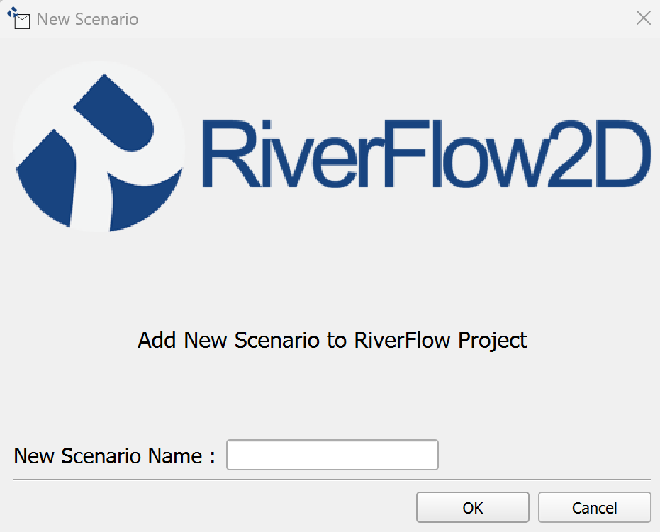
The New Scenario dialog prompts the user for the name of the new scenario and allows selection of an existing scenario to use as a template.
Dialog Controls
| Control | Type | Description |
|---|---|---|
| Base Scenario | Combo box | Populated with the names of existing scenarios in the current project. The user selects the scenario to use as the template for the new one. |
| New Scenario Name | Text input field | Text input field where the user enters the desired name for the new scenario. |
| Ok | Button | Button to confirm the settings and create the new scenario. |
| Cancel | Button | Button to close the dialog without creating a new scenario. |
Workflow
-
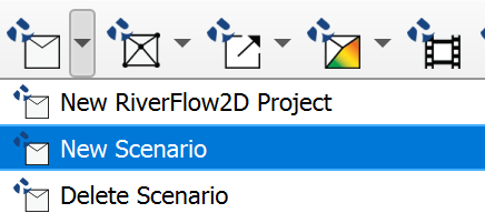
Open QGIS and click on the
icon and click on the New Scenario menu item.
-
The Add New New Scenario to Project dialog appears.
-
Enter a unique name for the New Scenario Name.
-
Click Ok.
-
A new scenario directory is created at the same level as the existing scenario directories:
project_folder\scenario_name\shape. -
The tool determines which files need to be copied.
-
Essential project files (GeoPackages, mesh files, shapefiles), are copied from the Base Scenario's and
/shapedirectories to the corresponding locations in the New Scenario directory. -
The plugin updates its internal list of scenarios (reflected in a scenario selection dropdown in the main interface).
-
The plugin switches the active scenario to the newly created one, unloading layers from the previous scenario and loading the corresponding layers from the new scenario's
shapedirectory.
Requirements
-
A RiverFlow2D MS project must be currently open in QGIS.
-
The project must contain at least one existing scenario to serve as the base.
-
A unique New Scenario Name must be provided. It cannot be empty or match an existing scenario name.
-
The user must have write permissions in the project directory.
Technical Details
-
Scenario Identification: Scenarios are identified by their folder names within the main project directory.
-
Data Duplication: The core action is file-based copying. It duplicates the structure, content and common data files (like GeoPackages). Does not copy any model output files or produced maps.
-
Active Scenario Switching: Involves unloading the layers associated with the previous scenario and loading the corresponding layers from the new scenario's directory by updating their data source paths.
Delete Scenario
This tool removes an existing scenario from the RiverFlow2D project. This action is irreversible but the files are not permanently deleted from the file system.
Dialog Window
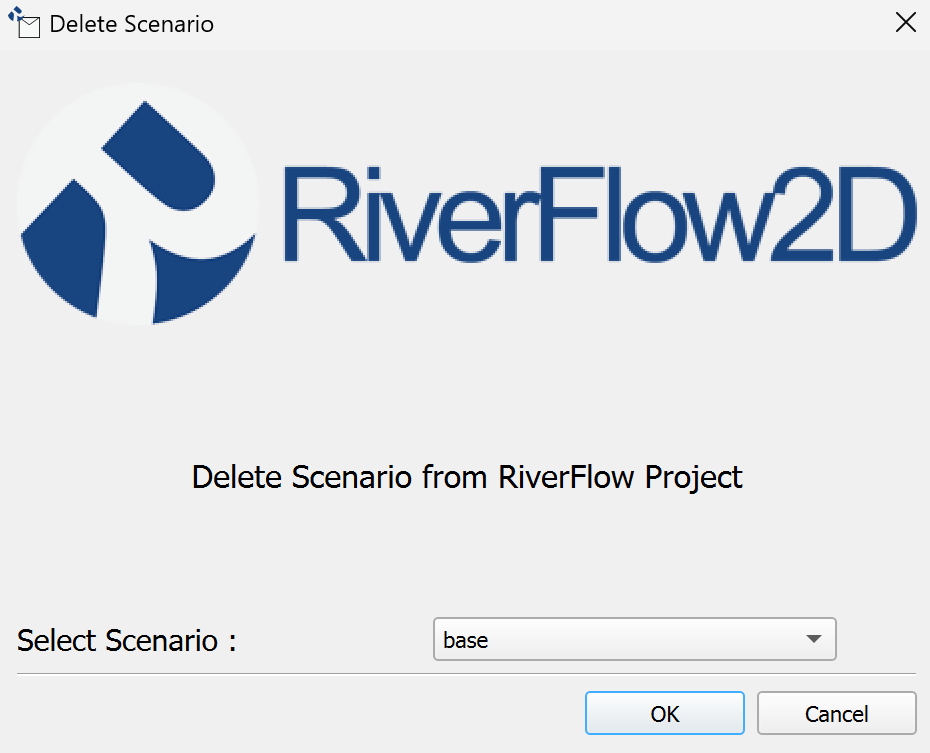
The Delete Scenario dialog allows the user to select which existing scenario to remove.
Dialog Controls
| Control | Type | Description |
|---|---|---|
| Select Scenario | Combo box | Populated with the names of existing scenarios in the current project. The user selects the scenario to be deleted. |
| Ok | Button | Button to confirm the selection and remove the chosen scenario from the project. |
| Cancel | Button | Button to close the dialog without removing any scenario. |
Workflow
-
Ensure a RiverFlow2D project is open and active.
-
Activate the tool, click on the
icon and click on the Delete Scenario menu item.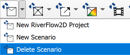
-
The Delete Scenario from RiverFlow2D Project dialog appears.
-
The Select Scenario dropdown list is populated with all existing scenarios.
-
Select the scenario you wish to remove from the dropdown list.
-
Click Ok.
-
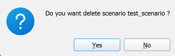
The user will receive a confirmation message asking them to confirm the removal.
-
Click Ok again to confirm the removal.
-
The tool identifies the directory path corresponding to the selected scenario, then removes the scenario from the project.
-
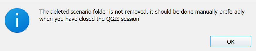
The user will receive a message indicating that the scenario has been removed from the project.
-
As the message indicates, this action is not permanently deleting files from the file system. If the user chooses, they can manually delete the entire directory in File Explorer. This will make it unrecoverable.
-
The plugin updates its internal list of scenarios, removing the deleted one (this is reflected in the scenario selection dropdown in the main interface).
-
Save your changes to the project to ensure that the changes are saved and no leftover artifacts are left behind.
Requirements
-
A RiverFlow2D MS project must be currently open in QGIS.
-
The project must contain at least two scenarios, as the currently active scenario cannot be deleted.
-
The user must select a scenario from the list.
-
The plugin will not allow the user to delete a scenario if it is the only one remaining in the project.
Manual Recovery of Deleted Scenario
If you need to recover a scenario that was deleted from the project but did not delete the old scenario directory, you can create a new scenario and manually copy the files back in.
-
Follow the steps in the 1.2 section to create a new scenario.
-
Save the project.
-
Close QGIS.
-
In File Explorer, navigate to the old scenario directory and copy the contents, not the directory itself.
-
Paste the files into the new scenario directory, overwriting the existing files.
-
Open QGIS and load the project.
-
The new scenario will be loaded with the copied files.
Technical Details
-
Files are left intact: The scenario directory and associated .qlr file is left intact. The user must manually delete the directory and .qlr file.
-
Cannot reuse deleted scenario name: Unless the user deletes the associated .qlr file and saves the project, the scenario name cannot be reused.
-
Interface Update: The scenario selection dropdown in the main plugin interface is updated to reflect the removal of the scenario.
-
Post-Deletion Active Scenario: The plugin automatically switches the active QGIS view to another existing scenario after the deletion is complete.